Showing posts with label garg. Show all posts

Thursday, 10 April 2014

Brakes: Design your own Disk Brakes - Part7

We all know drum brakes are an important part of life and learning to design them is extremely important but with the time of upgrading brakes into disc brakes, it is even more important that one must know the design aspects of disk brakes. In this article we will show how you can design your own disk brake and all the calculations and equations involved.
The above image represents a simple disc brakes and to understand the equations, one must understand the image above and now key to defining elements:
F = Force applied by the slave cylinder on the brake shoe
r = radius from center of disk to center of the brake pad
ro = radius from center to outer surface of the brake pad
ri = radius from center to inner radius of the brake pad
θ1 = angle from horizontal to heel of brake pad
θ2 = angle from horizontal to toe of brake pad
Pmax = maximum applied pressure (depends on frictional material)
P = Uniformly distributed pressure along brake pad
Now, one more things to take into account is, in disc brakes there are 2 conditions that persists! 1) Uniform Pressure: which is applicable for new brakes & 2) Uniform Wear: which comes after a certain amount of use. Now, Work done is directly proportional to Pmax X ri therefore, W = k.Pmax.ri and since W & k are constants, let, W/k = K = Pmax.ri, Also, K = P.r, therefore,
P = Pmax.ri/r
Now, the force applied on the brake pads (F) is equal to
F = 
Replacing P with equation above and doing integration for θ, we get;
F = 
Again, doing integration for radius r, we get;
F = 
The equation above gives the force, now for torque;
τ = 
Replacing P with Pmax equation and integrating for θ, we get;
τ = 
Again, integrating for radius r, we get;
τ = 
Thus, the above equation gives torque for the disc brakes for uniform wear system!
Now to get equivalent radius (re) = τ/µF 
All the above equations hold good for Uniform wear system when work done is dependent on radius but when the brakes are new, then P = Pmax because of which the new equations becomes;
F = 
Integrating for θ and solving for P, we get;
F = 
Thus, the final equations comes out to be;
F = 
Also for Torque (τ), the equations changes as;
τ = 
Integrating for θ and solving for P, we get;
τ = 
Thus, the final equation on integration of r comes out to be;
τ = 
With, this all the design equations have been discussed for the disc brakes, again, we know Torque = Force X Perpendicular length

Therefore, The Force applied by the force to stop the car will be Fbrake = τ / re
Using this, we can solve any linear motion problem and calculate stopping distance and find time to decelerate the vehicle from velocity v to 0 using equations of motion.

Sunday, 6 April 2014

Brakes: The Drag Brakes - Part5

Drag brakes as the name suggest are completely different braking system, both in characteristics and functioning! As the name suggests, it produces a force which opposes the motion of the vehicle. Drag in normal terms can be described as the force which is applied on a component of vehicle which does not fall in its aerodynamic foil. The ambient air at high speeds, due to relative motion of the vehicle against air, produces a massive amount of air channel in front of vehicle through which the vehicle has to go through else it'll hinder the top speed capacity of the vehicle. After a lot of research in the field of aerodynamics, the researchers mentioned that the shape of the "falling water drop" is the most aerodynamic shape and if somebody might have noticed, the shape of Airfoil is also shape of drop only.
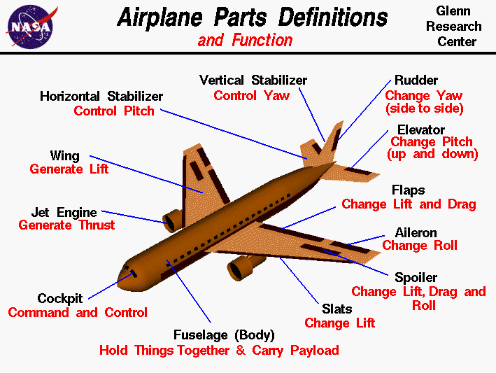
The most common application of drag brakes is aircraft, the common name of drag surface is spoiler in aircraft which is present above the flap and even flap functions somewhat as the drag brake. These are together called as control surfaces and they include: flaps, rudder, aileron, slats, spoilers and elevators which control the 6 degrees of freedom of the aircraft!
Courtesy to NASA

The basic concept of functioning is very simple, when flaps and spoilers are deployed, they work as resistance to the air flowing through the flat surface thus making air as the working medium to stop the vehicle.
The same concept has been used in cars for a very long time, the spoilers in cars does the same thing. There are two types of spoilers, 1) Fixed geometry: which is usually used to create downforce 2) Variable Geometry: also called as Retractable spoilers, they serve as both drag brake system as well as downforce producing system.
Both above images show different types of spoilers.
The above image shows a very conventional drag method to stop high speeding cars like the high tuned drag racing cars! In them, the designers and enthusiasts used to install the parachute behind the car with a deployment circuit through which the driver can deploy it whenever he wants to stop the car. Drag brakes in automotives have been very useful especially in the stopping distance timings of super cars like Bugatti Veyron. They make sure that the Peak force of the friction brakes are always under control!
So, with this we end with the types of braking system and their functioning, in next series we will start with the calculations involved in designing if each of the braking system and we will start from drum brakes.

Saturday, 5 April 2014

Brakes: Electromagnetic Brakes - Part4

Dear readers, I am sorry for the delay in 4th part of the brake series. Today we are going to talk about EM Brakes or Electromagnetic Brakes. We have already covered the basics, about disk brakes and about drum brakes in previous articles and they can be found in http://themechunicorn.blogspot.in/. So, let's come to the topic of EM Brakes, EM Brakes are usually seen in heavy vehicles like trams, trains etc. They serve as an alternative to friction brakes. The various advantages of EM brakes include high CPD (Continuous Power Dissipation) i.e. it's ability to remove excess heat energy very quickly thus increasing life span of system and reducing maintenance costs. In recent years, with development of hybrid and electric cars, the EM brakes have been used in  them also, and their functioning and construction is very different from conventional disk or drum friction brakes.
As can be seen from the image above, the EM brakes have a electric coil which produces controlled magnetic pole and energizes the Armature to have an opposite pole and with continuous change in strength, the magnetic forces push the armature towards the friction disk which produces the required braking action.
Now we will explain each component and their role in functioning of the EM brakes.
Lead Wire: It is the electrical wire that brings 24V or 12V DC from battery/alternator to the EM brakes coils.
EM Coil: On application of DC, the coil produces a magnetic force and pole on the concepts of Faraday's law of Electromagnetic Induction and Faraday-Maxwell Equation and also on Fleming's Right-Hand thumb rule.
Braking Spring: It is the return spring, after application of brakes and de-energizing of coils, the return brake springs detaches the armature from friction disks.
Friction disks: They are circular disks with friction material linings on outer surface, they are usually made of aluminium and are hollowed inside for maximum ambient air displacement and increased cooling effect on friction disk.
Hub: The component which attaches to the output shaft and finally with wheels.
The whole EM brake assembly is mounted on anti-vibration mountings in chassis and is fixed together with 3 fixed bolts. The EM brakes have a lot of advantages over conventional friction brakes and can be easily equipped with many other technologies like KERS (Kinetic Energy Regeneration System) to increase the efficiency and overall power of the whole vehicle.

Wednesday, 2 April 2014

Brakes: Drum Brakes - Part2

In the previous article, we talked about the basic concepts that are related with brakes and terminology that is defined to understand brakes and its features. The previous blog can be found at: http://themechunicorn.blogspot.in/2014/04/brakes-general-part1.html
Now, in this part, we will start discussing about the components and construction of different braking systems, we will start with the simplest friction based drum brakes for vehicle and will continue towards disk brakes, aircraft drag brakes, jake brakes and will end towards electromagnetic brakes. This differentiation will be based on categories depending upon the vehicle i.e. we will first take brake systems used in cars, then aircrafts and then other vehicles.

The two images above show a basic drum-brake assembly for cars and motorcycle. These are the most common braking system till now for vehicles but are now being replaced by disc brakes at a very fast rate, the reason for this migration is quite simple, high brake fade, low peak force, less brake power when compared to disc brakes and less durability. The drum brakes work on a very simple principle of friction. The drum-brake assembly include the following:
1) Brake Drum - It is the brake cover that gets attached to the wheel while also serving as the friction surface for the brake system, the inner side of the brake drum is lined with frictional surface having a friction coefficient (µ) of anything between 0.4 to .45 while depending upon application, the µ might gets increases as high as 0.66. Brake drum also connects with the tire and is subjected to high torque when braking action is required.
2) Brake Shoe - It is the component that is attached with the brake lining material of the inner assembly and the actuation occurs here itself, the hydraulic slave cylinder is connected to both the brake shoes and when brakes are actuated, the slave cylinder pushes the brake shoe towards the brake drum and the shoe returning springs bring it back after actuation is completed.
3) Shoe Adjustment: It is the component through which you can set the initial position of the brake shoe! It is used to control the pedal play as well as to control the peak force, but increasing the initial value of shoe might result in reduced durability due to increased drag and more brake power.
4) Hydraulic Slave Cylinder: It is the actuator unit of the drum brakes, apart from hydraulic actuators like hydraulic cylinders, various drum brake designs also use mechanical actuation which is still commonly seen in motorcycles. Through a hydraulic pipe it is directly connected with the master hydraulic cylinder which in turn is connected with the brake pedal! As hydraulic systems are based on Pascal's law, the rest of the actuation method is nothing but a series of clever engineering architecture.
The brake power is directly related to the surface area of the brake pads or brake lining material in contact with the inner brake lining of the brake drum. Now, a days the application of drum brakes have been reduced considerably and are usually used as secondary braking system like the parking brakes while newer disk brakes have taken the place as primary braking system in the cars.
Thus, with this we conclude the information related to drum brakes, in next series of article, we will talk about other types of brakes and their constructions. Also, we will also bring in all the equations related to drum brakes and their designs in upcoming articles so that entrepreneuring designers can use the resources for designing their own drum brake systems and innovate!

Monday, 31 March 2014

Everything about Turbo chargers!

We usually read in brochures of diesel cars, VGT or might have heard in fast and furious series the term: Turbochargers! but what exactly are they and how they work is a good question! Few car enthusiasts might be knowing something about it but in this blog, we will talk about anything and everything for Turbochargers. In this blog we will cover the basics of turbochargers, their types, cooling methodologies and finally applications. So, let's start!
Well in simple words, a turbocharger is a forced induction device i.e. it converts the linear motion of exhausts gas out from the exhaust manifold of the engine and converts it into rotary motion of turbine which in turn increases the air-intake in the inlet manifold for better performance of the engine. As we know, more air means more perfect fuel combustion which in turn increases mechanical efficiency!
The reaction involved inside combustion chamber of iso-octane with oxygen is:
C8H18 + 12.5 O2 ------ 8 CO2 + 9 H2O
As, can be seen in the above equation, for every mole of iso-octane/fuel; 12.5 moles of pure oxygen is required to completely burn the fuel else:
C8H18 + 10 O2 ------ 8 CO2 + 4 H2O + 5 H2 or even,
C8H18 + 5 O2 ------ 4 CO2 + H2O + CO + 3 CH4 + 2 H2
if the fuel if not burned properly, then there will be carbon monoxide, methane and unburned hydrogen which escape to atmosphere and is not good for environment. There are 2 air-fuel mixtures: 1) Lean i.e. more amount of air than usual 14.7:1 stoichiometric air-to-fuel ratio (AFR) or 2) Rich i.e. more amount of fuel in AFR. Well, they are there in Automobile dictionary for some reason. The reason is, lean AFR will result in more mechanical efficiency and cleaner exhaust while richer AFR will provide with more torque. But, more of something is also dangerous, the lean or rich AFR must be set optimally for best results! In an un-tuned turbocharged engine, the AFR is overly-lean which increases probability of knocking so in such-cases the AFR is made richer!
Now, there are various types of turbochargers (and I mean turbochargers; don't mix it up with superchargers or twin-chargers). The various types are:
1) Twin-Turbo - which means that two different turbochargers are used sequentially or parallel. If the turbos are parallel, it means the exhaust from different cylinders split into each i.e. let's say in a V6 arrangement: the cylinders 1,3,5 will be connected to 1st turbo while cylinders 2,4,6 will be connected to 2nd turbocharger! The main benefit of connecting two parallel turbos is that, the turbo-lag is reduced considerably while reducing the size they take up in the chassis; the other arrangement is to connect twin-turbo sequentially. This arrangement usually uses two different sized turbos, first a small turbo to reduce initial turbo lag and second big turbo to provide peak performance during full throttle, that is also the reason they are called as 2-stage twin turbo!
2) Twin-Scroll - or divided turbochargers instill the properties of 2-stage turbo into 1. The twin-scroll turbocharger has 2 exhaust-inlet manifolds and 2 nozzles. The sharp angled nozzle is for quick response and reduction in turbo-lag while the other division is for peak performance.
3) Variable Geometry - The Variable Geometry Turbocharger or VGT uses multi vane nozzle to control the exhaust-air flow to turbin and uses an actuator to control the diameter opening of nozzle. This gives a optimal power curve throughout the size which helps reduce lag without compensating for either boosted acceleration or boosted torque at peak revs!
Well, they might put you racing but without the underlying accessories, you might wanna race in tonight's race because you might loose your engine or blow off your car!
1) Intercooler: It is the most useful and essentially the most required addition you might want to install with your turbocharger! When, the air is forced into the inlet-manifold its pressure and temperature increases, thus reducing the density of oxygen in the air-fuel mixture thus, to optimise it an air charge intercooler is fitted with every turbocharger to increase the density of the air-fuel mixture and increase efficiency of the turbo-charger, also while bringing temperature under control.
2) Water Injection system: though not-popular and even very cumbersome, the water injection system is an alternative to intercooler which reduces the temperature of inlet-air through injecting water, this system was used in various automobile and aircraft applications.
3) External Waste Gate: A wastegate is a solenoid operated device that redirects excess of exhaust air away from turbine so as to regulate the power output of a small turbocharger and save engine and turbocharger from excess wear and breakdown.
4)Dump Valve: also anti-surge valve or blow off valve is a auto-pressure release valve that reduces the pressure when suddenly the throttle valve is closed in a wide-open throttle engine system. When the throttle is closed, the compressed air has no exit and without dump valve might result catastrophic in nature that is why the dump valve is an required accessory in turbochargers.
Now, since we've talked about basic working of turbo, its types, additions, then now it is right time to talk about the applications. The turbochargers have been used widely across all locomotives from production road cars to aircrafts.
1) Petrol Engines: Since 1962 Oldsmobile Jetfire Turbo to 2014 Mclaren P1, all possess petrol turbocharged engines which increase their power output by many folds.
2) Diesel Engine: The application of turbochargers in diesel engines came in 1978's with the Mercedes 300SD which drastically improved the fuel efficiency, mechanical efficiency, and driveability of diesel cars.
3) Aircrafts: Otto as well as Brayton cycle engines, both require forced induced air in one way or another; as altitude increases inversely, the density of oxygen in air increases thus making it difficult for engine to aspire, thus since 1920's research on using turbochargers with aircraft's rotary spark ignition engine started! the same concept of turbochargers is used in brayton cycle engines also where the air is compressed axially rather than using a centrifugal system.
Apart from these main uses, turbochargers have been extensively used in motorcycles, trucks, marine and land machinery etc.