Showing posts with label drag. Show all posts

Sunday, 6 April 2014

Brakes: The Drag Brakes - Part5

Drag brakes as the name suggest are completely different braking system, both in characteristics and functioning! As the name suggests, it produces a force which opposes the motion of the vehicle. Drag in normal terms can be described as the force which is applied on a component of vehicle which does not fall in its aerodynamic foil. The ambient air at high speeds, due to relative motion of the vehicle against air, produces a massive amount of air channel in front of vehicle through which the vehicle has to go through else it'll hinder the top speed capacity of the vehicle. After a lot of research in the field of aerodynamics, the researchers mentioned that the shape of the "falling water drop" is the most aerodynamic shape and if somebody might have noticed, the shape of Airfoil is also shape of drop only.
The most common application of drag brakes is aircraft, the common name of drag surface is spoiler in aircraft which is present above the flap and even flap functions somewhat as the drag brake. These are together called as control surfaces and they include: flaps, rudder, aileron, slats, spoilers and elevators which control the 6 degrees of freedom of the aircraft!
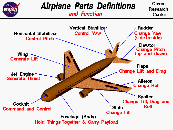
Courtesy to NASA

The basic concept of functioning is very simple, when flaps and spoilers are deployed, they work as resistance to the air flowing through the flat surface thus making air as the working medium to stop the vehicle.
The same concept has been used in cars for a very long time, the spoilers in cars does the same thing. There are two types of spoilers, 1) Fixed geometry: which is usually used to create downforce 2) Variable Geometry: also called as Retractable spoilers, they serve as both drag brake system as well as downforce producing system.
Both above images show different types of spoilers.
The above image shows a very conventional drag method to stop high speeding cars like the high tuned drag racing cars! In them, the designers and enthusiasts used to install the parachute behind the car with a deployment circuit through which the driver can deploy it whenever he wants to stop the car. Drag brakes in automotives have been very useful especially in the stopping distance timings of super cars like Bugatti Veyron. They make sure that the Peak force of the friction brakes are always under control!
So, with this we end with the types of braking system and their functioning, in next series we will start with the calculations involved in designing if each of the braking system and we will start from drum brakes.

Saturday, 5 April 2014

Brakes: Electromagnetic Brakes - Part4

Dear readers, I am sorry for the delay in 4th part of the brake series. Today we are going to talk about EM Brakes or Electromagnetic Brakes. We have already covered the basics, about disk brakes and about drum brakes in previous articles and they can be found in http://themechunicorn.blogspot.in/. So, let's come to the topic of EM Brakes, EM Brakes are usually seen in heavy vehicles like trams, trains etc. They serve as an alternative to friction brakes. The various advantages of EM brakes include high CPD (Continuous Power Dissipation) i.e. it's ability to remove excess heat energy very quickly thus increasing life span of system and reducing maintenance costs. In recent years, with development of hybrid and electric cars, the EM brakes have been used in  them also, and their functioning and construction is very different from conventional disk or drum friction brakes.
As can be seen from the image above, the EM brakes have a electric coil which produces controlled magnetic pole and energizes the Armature to have an opposite pole and with continuous change in strength, the magnetic forces push the armature towards the friction disk which produces the required braking action.
Now we will explain each component and their role in functioning of the EM brakes.
Lead Wire: It is the electrical wire that brings 24V or 12V DC from battery/alternator to the EM brakes coils.
EM Coil: On application of DC, the coil produces a magnetic force and pole on the concepts of Faraday's law of Electromagnetic Induction and Faraday-Maxwell Equation and also on Fleming's Right-Hand thumb rule.
Braking Spring: It is the return spring, after application of brakes and de-energizing of coils, the return brake springs detaches the armature from friction disks.
Friction disks: They are circular disks with friction material linings on outer surface, they are usually made of aluminium and are hollowed inside for maximum ambient air displacement and increased cooling effect on friction disk.
Hub: The component which attaches to the output shaft and finally with wheels.
The whole EM brake assembly is mounted on anti-vibration mountings in chassis and is fixed together with 3 fixed bolts. The EM brakes have a lot of advantages over conventional friction brakes and can be easily equipped with many other technologies like KERS (Kinetic Energy Regeneration System) to increase the efficiency and overall power of the whole vehicle.

Wednesday, 2 April 2014

Brakes: Drum Brakes - Part2

In the previous article, we talked about the basic concepts that are related with brakes and terminology that is defined to understand brakes and its features. The previous blog can be found at: http://themechunicorn.blogspot.in/2014/04/brakes-general-part1.html
Now, in this part, we will start discussing about the components and construction of different braking systems, we will start with the simplest friction based drum brakes for vehicle and will continue towards disk brakes, aircraft drag brakes, jake brakes and will end towards electromagnetic brakes. This differentiation will be based on categories depending upon the vehicle i.e. we will first take brake systems used in cars, then aircrafts and then other vehicles.

The two images above show a basic drum-brake assembly for cars and motorcycle. These are the most common braking system till now for vehicles but are now being replaced by disc brakes at a very fast rate, the reason for this migration is quite simple, high brake fade, low peak force, less brake power when compared to disc brakes and less durability. The drum brakes work on a very simple principle of friction. The drum-brake assembly include the following:
1) Brake Drum - It is the brake cover that gets attached to the wheel while also serving as the friction surface for the brake system, the inner side of the brake drum is lined with frictional surface having a friction coefficient (µ) of anything between 0.4 to .45 while depending upon application, the µ might gets increases as high as 0.66. Brake drum also connects with the tire and is subjected to high torque when braking action is required.
2) Brake Shoe - It is the component that is attached with the brake lining material of the inner assembly and the actuation occurs here itself, the hydraulic slave cylinder is connected to both the brake shoes and when brakes are actuated, the slave cylinder pushes the brake shoe towards the brake drum and the shoe returning springs bring it back after actuation is completed.
3) Shoe Adjustment: It is the component through which you can set the initial position of the brake shoe! It is used to control the pedal play as well as to control the peak force, but increasing the initial value of shoe might result in reduced durability due to increased drag and more brake power.
4) Hydraulic Slave Cylinder: It is the actuator unit of the drum brakes, apart from hydraulic actuators like hydraulic cylinders, various drum brake designs also use mechanical actuation which is still commonly seen in motorcycles. Through a hydraulic pipe it is directly connected with the master hydraulic cylinder which in turn is connected with the brake pedal! As hydraulic systems are based on Pascal's law, the rest of the actuation method is nothing but a series of clever engineering architecture.
The brake power is directly related to the surface area of the brake pads or brake lining material in contact with the inner brake lining of the brake drum. Now, a days the application of drum brakes have been reduced considerably and are usually used as secondary braking system like the parking brakes while newer disk brakes have taken the place as primary braking system in the cars.
Thus, with this we conclude the information related to drum brakes, in next series of article, we will talk about other types of brakes and their constructions. Also, we will also bring in all the equations related to drum brakes and their designs in upcoming articles so that entrepreneuring designers can use the resources for designing their own drum brake systems and innovate!

Tuesday, 1 April 2014

Brakes: The General - Part1

In these series of blogs, we are gonna discuss everything and anything about brakes, starting from terminology and basics involved in first blog to its calculations and how entrepreneur designers can design their own locomotives. Since Brakes are one of the most important 3 mechanisms of any locomotive, other being power generation and steering mechanism; So, we will give time and explain everything about them gradually! So, let's start with the basics! What is a brake? In easiest words, a system or device that reduces or halts motion. Taking example of cars; brakes reduces the speed of a moving car and eventually brings it to a complete halt. Now, there are various types of braking methodologies, 1) Friction Brakes: The brakes use friction to bring out braking action and usual example include drum brakes, disk brakes, hydraulic disk brakes & pneumatic disc brakes. 2) Pumping Brakes: which use engine and engine's components friction as the required braking action! The most popular ans simple type of Pumping brake is Jake Brake which open the exhaust valve during the expansion stroke of Engine. 3) Electromagnetic Brakes: They bring about the braking action using electromagnets, they are commonly installed in hybrid/electric vehicles and is also the basis of KERS (Kinetic Energy Regeneration System) in cars. 4) Drag Brakes: These types of brakes find their application in vehicles which require deceleration through a fluid medium like air or water; the easiest example is the flaps in the wings of aircraft.
courtesy to www.images.google.com
The above image shows a typical disc-drum arrangement in a modern car and the various components involved in them! In the continuing articles we will explain functioning and detailed information about each component but for basics, I believe, its the best way to understand the braking system. Now, let's talk about some terminology one should know while studying brakes.
1) Peak Force: The peak force is the maximum amount of decelerating effect that can be achieved by the system. The peak force is usually greater than the traction limit value of tyres which results in wheel skid when brakes are applied with full force. The peak force depends on the friction coefficient between the friction components of the braking system and the time of actuation or in drag brakes case: the angle of attack i.e. at which angle the actuated component is to the streamlined fluid.
2) Continuous Power Dissipation: It is commonly affiliated with friction brakes, on actuation a lot of heat energy is produced in the system and after a particular temperature the braking system might breakdown! Thus, the maximum amount of power a braking system can dissipate without breaking down is called as Continuous Power Dissipation. The dissipation is dependent on temperature and speed of ambient cooling air.
3) Brake Fade: Because of increase in temperature, the brakes efficiency might reduce, which is technically termed as Brake fade. It is dependent on the design, and cooling system of brake plays a very important role in determining the Brake Fade of the system.
4) Smoothness: It is more of a physical term than technical term for brake application. It's all about the experience of the driver, if the brakes are harsh, worn out and exert unequal force will produce skids and would be unappreciated by the driver as such system will make him experience that he is driving on a camel.
5) Power: It is the amount of brake force the system produces with respect to the application of brake pedal! In other way, it is the ability of the system that how fast can it reach its Peak Force.
6) Drag: It is the incomplete detachment of one braking component with another because of which the unwanted braking action might be there even during full pedal release. The common causes of drag are misaligned brake shoes, broken springs, over-extended actuator wire or piston failure etc.
7) Durability: Brake systems have frictional parts that wear out at every application of brake and might needs to be replaced from time to time. The durability of systems with higher peak force is lesser.
Well, these are the most important terminology one must know in order to understand braking and braking systems! The braking system is specifically mounted on either wheel or trans-axle depending on application of the braking system. One thing that one must also know is that braking system which may/may not include supporting structure adds into weight of the body thus, it also plays an important factor depending on application. With this, we end our first article on basics of brakes and keep tuned for the next article which will briefly explain each component of braking systems and application-wise differences in them.