Well, we are nearly at the end of series with few more articles to go! Till date, we have already discussed nearly everything about construction, advantages, disadvantages and uses of each braking system but we, The Unicorn, understands that just understanding is not enough for anyone that is why we also make you understand how you can design the system yourself! As our motto says, Educate, Excel and then Innovate! To innovate you need to learn everything including how to design the system and the equations involved. In this article we will discuss the design aspects and equations involved in designing drum brakes.
 Θ1 = angle from center of pivot point to heel of shoe lining
To understand the design aspects of drum brakes, we have to understand the image above! First of all, as assumed we will say that direction of rotation of wheel is clockwise. Now the key to defining elements:
F = Force applied by the actuating device on each of the brake shoes.
Pmax = Maximum Pressure applied
c = total displacement of heel and toe of the brake shoe
a = displacement from center of drum to the center axis of the brake shoe
r = radius of the drum from center of drum
b = displacement from center axis to the pivot point
Θ2 = angle from center of pivot point to toe of shoe lining
Θ = average angle to distribute forces along the whole length of the shoe
and let µ = frictional coefficient of the shoe lining material
let's take k = Pmax/SinΘ2 therefore, k = P/sinΘ
equating both, we get; P = PmaxsinΘ/sinΘ2 (where P is Uniformly distributed Pressure)
Now, Let Mf be the Moment of Inertia due to Frictional Force then,
Mf = 
Replacing P, we get:
Mf = 
Therefore, final formula after integration comes out to be:
Mf = 
Now, for calculating Moment of Inertia for Normal Force,
Mn = 
Replacing P in above equation,
Mn = 
After integration, final formula comes out to be:
Mn = 
Therefore, F = (Mf - Mn)/c
Also, Torque applied by the right shoe will be equal to
τr = 
replacing P, we get:
τr = 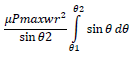
The final equation becomes:
τr = 
Also, we need to add the force due to Left Shoe also called the trailing shoe;
For trailing shoe P'max = FcPmax/(Mf + Mn)
The torque applied by the left shoe will be:
τl = 
replacing P', the above equation becomes:
τl = 
The final equation becomes:
τl = 
The total Torque τ = τr + τl
Also, we know Torque = Force X Perpendicular length
Therefore, The Force applied by the force to stop the car will be Fbrake = τ / Radius of Drum
Using this, we can solve any linear motion problem and calculate stopping distance and find time to decelerate the vehicle from velocity v to 0 using equations of motion.