We all know drum brakes are an important part of life and learning to design them is extremely important but with the time of upgrading brakes into disc brakes, it is even more important that one must know the design aspects of disk brakes. In this article we will show how you can design your own disk brake and all the calculations and equations involved.

The above image represents a simple disc brakes and to understand the equations, one must understand the image above and now key to defining elements:
F = Force applied by the slave cylinder on the brake shoe
r = radius from center of disk to center of the brake pad
ro = radius from center to outer surface of the brake pad
ri = radius from center to inner radius of the brake pad
θ1 = angle from horizontal to heel of brake pad
θ2 = angle from horizontal to toe of brake pad
Pmax = maximum applied pressure (depends on frictional material)
P = Uniformly distributed pressure along brake pad
Now, one more things to take into account is, in disc brakes there are 2 conditions that persists! 1) Uniform Pressure: which is applicable for new brakes & 2) Uniform Wear: which comes after a certain amount of use. Now, Work done is directly proportional to Pmax X ri therefore, W = k.Pmax.ri and since W & k are constants, let, W/k = K = Pmax.ri, Also, K = P.r, therefore,
P = Pmax.ri/r
Now, the force applied on the brake pads (F) is equal to
F = 
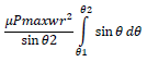
Replacing P with equation above and doing integration for θ, we get;
F = 
Again, doing integration for radius r, we get;
F = 
The equation above gives the force, now for torque;
τ = 
Replacing P with Pmax equation and integrating for θ, we get;
τ = 
Again, integrating for radius r, we get;
τ = 
Thus, the above equation gives torque for the disc brakes for uniform wear system!
Now to get equivalent radius (re) = τ/µF
All the above equations hold good for Uniform wear system when work done is dependent on radius but when the brakes are new, then P = Pmax because of which the new equations becomes;
F = 
Integrating for θ and solving for P, we get;
F = 
Thus, the final equations comes out to be;
F = 
Also for Torque (τ), the equations changes as;
τ = 
Integrating for θ and solving for P, we get;
τ = 
Thus, the final equation on integration of r comes out to be;
τ = 
With, this all the design equations have been discussed for the disc brakes, again, we know Torque = Force X Perpendicular length
Therefore, The Force applied by the force to stop the car will be Fbrake = τ / re
Using this, we can solve any linear motion problem and calculate stopping distance and find time to decelerate the vehicle from velocity v to 0 using equations of motion.